Nov 6, 2011

Abstract of CCNA study guide-6 - tcp/ip 1

Continue the series of  Abstract CCNA study guide book .
Introduction to TCP/IP
TCP/IP and the DoD Model
The DoD model is composed of four layers:
-        Process/Application layer
-        Host-to-Host layer
-        Internet layer
-        Network Access layer

Next Figure  shows a comparison of the DoD model and the OSI reference model.


The Process/Application layer replaces the top three layers (Application, Presentation, and Session).
The Host-to-Host layer parallels the functions of the OSI’s Transport layer.
The Internet layer corresponds to the OSI’s Network layer
The Network Access layer equivalent of the Data Link and Physical layers of the OSI model
Figure below shows the TCP/IP protocol suite and how its protocols relate to the DoD model layers.


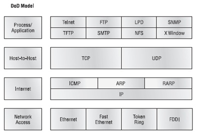
The Process/Application Layer Protocols
In this section, I’ll describe the different applications and services typically used in IP networks.
The following protocols and applications are covered in this section:
Telnet – FTP – TFTP – DNS  – DHCP/BootP – SMTP– SNMP– LPD - NFS - X Window

Telnet
Telnet is terminal emulation. It allows a user on a remote client machine, called the Telnet client, to access the resources of another machine

File Transfer Protocol (FTP)
File Transfer Protocol (FTP) is the protocol that actually lets us transfer files, and it can accomplish this between any two machines using it. But FTP isn’t just a protocol; it’s also a program.
FTP’s functions are limited to listing and manipulating directories, typing file contents, and copying files between hosts. It can’t execute remote files as programs.

Trivial File Transfer Protocol (TFTP)
Trivial File Transfer Protocol (TFTP) is the stock version of FTP. it’s so easy to use and it’s fast too. it can do nothing but send and receive files.

Domain Name Service (DNS)
Domain Name Service (DNS) resolves hostnames, specifically Internet names such as www.routersim.com

Dynamic Host Configuration Protocol (DHCP)/Bootstrap Protocol (BootP)
Dynamic Host Configuration Protocol (DHCP) assigns IP addresses to hosts.
DHCP differs from BootP in that BootP assigns an IP address to a host but the host’s hardware address must be entered manually in a BootP table. But remember that BootP is also used to send an operating system that a host can boot from. DHCP can’t do that.
there is a lot of information a DHCP server can provide to a host as :
IP address - Subnet mask - Domain name - Default gateway (routers) – DNS - WINS information.
A client that sends out a DHCP Discover message in order to receive an IP address sends out a broadcast at both layer 2 and layer 3. The layer 2 broadcast is all Fs in hex, which looks like this: FF:FF:FF:FF:FF:FF. The layer 3 broadcast is 255.255.255.255, which means all networks and all hosts. DHCP is connectionless, which means it uses User Datagram Protocol (UDP) at the Transport layer

Simple Mail Transfer Protocol (SMTP)
Simple Mail Transfer Protocol (SMTP) answering our ubiquitous call to email, uses a spooled, or queued, method of mail delivery. SMTP is used to send mail; POP3 is used to receive mail.

Simple Network Management Protocol (SNMP)
Simple Network Management Protocol (SNMP) collects and manipulates valuable network information.


The Host-to-Host Layer Protocols
This is still considered layer 4, and Cisco really likes the way layer 4 can use acknowledgments, sequencing, and flow control.
The following sections describe the two protocols at this layer:
- Transmission Control Protocol (TCP)
- User Datagram Protocol (UDP)

Transmission Control Protocol (TCP)
Transmission Control Protocol (TCP) takes large blocks of information from an application and breaks them into segments. It numbers and sequences each segment so that the destination’s TCP stack can put the segments back into the order the application intended. After these segments are sent, TCP (on the transmitting host) waits for an acknowledgment of the receiving end’s TCP virtual circuit session, retransmitting those that aren’t acknowledged.

Before a transmitting host starts to send segments down the model, the sender’s TCP stack contacts the destination’s TCP stack to establish a connection. What is created is known as a virtual circuit. This type of communication is called connection-oriented.

TCP is a full-duplex, connection-oriented, reliable, and accurate protocol.

TCP Segment Format
Figure below shows the TCP segment format. The figure shows the different fields within the TCP header.

The TCP header is 20 bytes long, or up to 24 bytes with options. You need to understand what each field in the TCP segment is:
Source port The port number of the application on the host sending the data.

Destination port The port number of the application requested on the destination host.

Sequence number A number used to puts the data back in the correct order or retransmits missing or damaged data.

Acknowledgment number The TCP octet that is expected next.

Header length The number of 32-bit words in the TCP header. This indicates where the data begins.

Reserved Always set to zero.

Code bits Control functions used to set up and terminate a session.

Window The window size the sender is willing to accept, in octets.

Checksum The cyclic redundancy check (CRC), The CRC checks the header and data fields.

Urgent A valid field only if the Urgent pointer in the code bits is set. If so, this value indicates the offset from the current sequence number, in octets, where the first segment of non-urgent data begins.

Options May be 0 or a multiple of 32 bits, if any.

Data includes the upper-layer headers.

User Datagram Protocol (UDP)
User Datagram Protocol (UDP) fabulous job is transporting  information that doesn’t require reliable delivery.
There are some situations in which it would be wise for developers to use UDP rather than TCP:
1- The cost in overhead to establish, maintain, and close a TCP connection for each one of those little messages would reduce efficient network as in SNMP.
2- When reliability is already handled at the Process/Application layer. Network File System (NFS) handles its own reliability issues, making the use of TCP both impractical and redundant.

UDP does not sequence the segments and does not care in which order the segments arrive at the destination.
And  after that, It doesn’t follow through, check up on them, or even allow for an acknowledgment of arrival
Because of this, it’s referred to as an unreliable protocol.

UDP doesn’t create a virtual circuit, nor does it contact the destination before delivering information to it. Because of this, it’s also considered a connectionless protocol.

This gives an application developer a choice when running the Internet Protocol stack: TCP for reliability or UDP for faster transfers.

So if you’re using Voice over IP (VoIP), for example, you really don’t want to use UDP, because if the segments arrive out of order , the result is seriously garbled data. On the other hand, TCP sequences the segments so they get put back together in exactly the right order.

UDP Segment Format
Look at the next figure carefully, can you see that UDP doesn’t use windowing or provide for acknowledgments in the UDP header?

It’s important for you to understand what each field in the UDP segment is:
Source port Port number of the application on the host sending the data
Destination port Port number of the application requested on the destination host
Length Length of UDP header and UDP data
Checksum Checksum of both the UDP header and UDP data fields
Data Upper-layer data

Key Concepts of Host-to-Host Protocols
Table below highlights some of the key concepts that you should keep in mind regarding these two protocols. You should memorize this table.


Port Numbers
TCP and UDP must use port numbers to communicate with the upper layers.
Figure below illustrates how both TCP and UDP use port numbers.


The different port numbers that can be used are explained next:
-Numbers below 1024 are considered well-known port numbers.
-Numbers 1024 and above are used by the upper layers to set up sessions with other hosts and by TCP to use as source and destination addresses in the TCP segment.

Table below gives you a list of the typical applications used in the TCP/IP suite, their well known port numbers, and the Transport layer protocols used by each application or process. It’s important to study and memorize this table.

Notice that DNS uses both TCP and UDP. Whether it opts for one or the other depends on what it’s trying to do. Even though it’s not the only application that can use both protocols, it’s certainly one that you should remember in your studies.

Nov 3, 2011

Abstract of CCNA study guide-5 - internetworking 5

Continue the series of  Abstract CCNA study guide book .
Data Encapsulation
To communicate and exchange information, each layer uses Protocol Data Units (PDUs). These hold the control information attached to the data at each layer of the model. They are usually attached to the header in front of the data field but can also be in the trailer.

PORT NUMBER
The Transport layer uses port numbers to define both the virtual circuit and the upper-layer process, as you can see from Figure 1.30.
If you’re using TCP, the virtual circuit is defined by the source port number. Remember, the host just makes this up starting at port number 1024 (0 through 1023 are reserved for well-known port numbers). The destination port number defines the upper-layer process (application) that the data stream is handed to when the data stream is reliably rebuilt on the receiving host.
The Cisco Three-Layer Hierarchical Model
The Cisco hierarchical model can help you design, implement, and maintain a scalable, reliable, cost-effective hierarchical internetwork. Cisco defines three layers of hierarchy, as shown in next Figure , each with specific functions.
The following are the three layers and their typical functions:
- The core layer: backbone
- The distribution layer: routing
- The access layer: switching
Remember, however, that the three layers are logical and are not necessarily physical devices.
when we build physical implementations of hierarchical networks, we may have many devices in a single layer, or we might have a single device performing functions at two layers.
Now, let’s take a closer look at each of the layers.
The Core Layer
the core layer is responsible for transporting large amounts of traffic both reliably and quickly.
The only purpose of the network’s core layer is to switch traffic as fast as possible.
There is some things we don’t want to do in core layer:
- Don’t do anything to slow down traffic as access lists, VLANs.
- Don’t support workgroup access here.
- Avoid expanding the core (i.e., adding routers).
Now, there are a few things that we want to do as we design the core:
- high reliability.
- Design with speed in mind.
- Select routing protocols with lower convergence times.
The Distribution Layer
The distribution layer is sometimes referred to as the workgroup layer
The primary functions of the distribution layer are to provide routing, filtering, and WAN access and to determine how packets can access the core.
There are several actions that generally should be done at the distribution layer:
- Routing
- Implementing tools (such as access lists), packet filtering, and queuing
- Implementing security and network policies, including address translation and firewalls
- Redistributing between routing protocols, including static routing
- Routing between VLANs and other workgroup support functions
- Defining broadcast and multicast domains
Things to avoid at the distribution layer are limited to those functions that exclusively belong to one of the other layers.
The Access Layer
The access layer controls user and workgroup access to internetwork resources. The access
layer is sometimes referred to as the desktop layer.
The following are some of the functions to be included at the access layer:
- Continued (from distribution layer) use of access control and policies
- Creation of separate collision domains (segmentation)
- Workgroup connectivity into the distribution layer
Technologies such as DDR and Ethernet switching are frequently seen in the access layer. Static routing (instead of dynamic routing protocols) is seen here as well.

Abstract of CCNA study guide-4 - internetworking 4

Continue the series of  Abstract CCNA study guide book .
Ethernet Cabling

Three types of Ethernet cables are available:
- Straight-through cable
- Crossover cable
- Rolled cable
Straight-Through Cable
The straight-through cable is used to connect
- Host to switch or hub
- Router to switch or hub

Four wires are used in straight-through cable to connect Ethernet devices.
Next Figure shows the four wires used in a straight-through Ethernet cable.
Notice that only pins 1, 2, 3, and 6 are used. Just connect 1 to 1, 2 to 2, 3 to 3, and 6 to 6 .
Crossover Cable
The crossover cable can be used to connect
- Switch to switch
- Hub to hub
- Host to host
- Hub to switch
- Router direct to host
The same four wires are used in this cable as in the straight-through cable.
We connect pins 1 to 3 and 2 to 6 on each side of the cable.
Rolled Cable
Although rolled cable isn’t used to connect any Ethernet connections together, you can use a rolled Ethernet cable to connect a host to a router console serial communication (com) port.
If you have a Cisco router or switch, you would use this cable to connect your PC running HyperTerminal to the Cisco hardware. Eight wires are used in this cable to connect serial devices.
Once you have the correct cable connected from your PC to the Cisco router or switch, you can start HyperTerminal to create a console connection and configure the device. Set the configuration as follows:
1. Open HyperTerminal and enter a name for the connection.
2. Choose the communications port—either COM1 or COM2.
3. Now set the port settings. The default values (2400bps and no flow control hardware) will not work;

Abstract of CCNA study guide-3- internetworking 3

Continue the series of  Abstract CCNA study guide book .
Ethernet Networking
Ethernet is a contention media access method that allows all hosts on a network to share the same bandwidth of a link.
Ethernet uses both Data Link and Physical layer specifications, and this section of the chapter will give you both the Data Link layer and Physical layer information you need to effectively implement, troubleshoot,and maintain an Ethernet network.

Ethernet networking uses Carrier Sense Multiple Access with Collision Detection (CSMA/CD), a protocol that helps devices share the bandwidth evenly without having two devices transmit at the same time on the network medium. CSMA/CD was created to overcome the problem of those collisions that occur when packets are transmitted simultaneously from different nodes.
Only bridges and routers can effectively prevent a transmission from propagating throughout the entire network!
When a host wants to transmit over the network, it first checks for the presence of a digital signal on the wire. If all is clear (no other host is transmitting), the host will then proceed with its transmission. But it doesn’t stop there. The transmitting host constantly monitors the wire to make sure no other hosts begin transmitting. If the host detects another signal on the wire, it sends out an extended jam signal that causes all nodes on the segment to stop sending data (think busy signal). The nodes respond to that jam signal by waiting a while before attempting to transmit again.
Backoff algorithms determine when the colliding stations can retransmit. If collisions keep occurring after 15 tries, the nodes attempting to transmit will then timeout.
When a collision occurs on an Ethernet LAN, the following happens:
- A jam signal informs all devices that a collision occurred.
- The collision invokes a random backoff algorithm.
- Each device on the Ethernet segment stops transmitting for a short time until the timers expire.
- All hosts have equal priority to transmit after the timers have expired.
The following are the effects of having a CSMA/CD network sustaining heavy collisions:
- Delay
- Low throughput
- Congestion
Half- and Full-Duplex Ethernet
Half-duplex Ethernet is defined in the original 802.3 Ethernet; Cisco says it uses only one wire pair with a digital signal running in both directions on the wire. It also uses the CSMA/CD protocol to help prevent collisions and to permit retransmitting if a collision does occur.
If a hub is attached to a switch, it must operate in half-duplex mode because the end stations must be able to detect collisions.
Half-duplex Ethernet—typically 10BaseT—is only about 30 to 40 percent efficient as Cisco sees it because a large 10BaseT network will usually only give you 3 to 4Mbps, at most.
full-duplex Ethernet uses two pairs of wires instead of one wire pair like half duplex.
And full duplex uses a point-to-point connection between the transmitter of the transmitting device and the receiver of the receiving device. And because the transmitted data is sent on a different set of wires than the received data, no collisions will occur.
Full-duplex Ethernet is supposed to offer 100 percent efficiency in both directions—for example, you can get 20Mbps with a 10Mbps Ethernet running full duplex or 200Mbps for Fast Ethernet.
Full-duplex Ethernet can be used in three situations:
- With a connection from a switch to a host
- With a connection from a switch to a switch
- With a connection from a host to a host using a crossover cable
Full-duplex Ethernet requires a point-to-point connection when only two nodes are present. You can run full-duplex with just about any device except a hub.
when a full-duplex Ethernet port is powered on, it first connects to the remote end and then negotiates with the other end of the Fast Ethernet link. This is called an auto-detect mechanism.
This mechanism first decides on the exchange capability, which means it checks to see if it can run at 10 or 100Mbps.
It then checks to see if it can run full duplex, and if it can’t, it will run half duplex.
Lastly, remember these important points:
- There are no collisions in full-duplex mode.
- A dedicated switch port is required for each full-duplex node.
- The host network card and the switch port must be capable of operating in full-duplex mode.
Ethernet at the Data Link Layer
Ethernet at the Data Link layer is responsible for hardware addressing or MAC addressing.
Ethernet is also responsible for framing packets received from the Network layer and preparing them for transmission on the local network
Ethernet Addressing
Ethernet uses the Media Access Control (MAC) address burned into each and every Ethernet network interface card (NIC). The MAC address is a 48-bit (6-byte) address written in a hexadecimal format.
Next Figure shows the 48-bit MAC addresses and how the bits are divided.
The organizationally unique identifier (OUI) is assigned by the IEEE to an organization.
It’s composed of 24 bits, or 3 bytes. The organization, in turn, assigns a globally administered address (24 bits, or 3 bytes) that is unique to each and every adapter it manufactures.
Look at the figure. The high-order bit is the Individual/Group (I/G) bit. When it has a value of 0, then the address is the MAC address of a device and when it is a 1, we can assume that the address represents either a broadcast or multicast address.
The next bit is the global/local bit, or just G/L bit, when set to 0, this bit represents a globally administered address (as by the IEEE). When the bit is a 1, it represents a locally governed and administered address.
The low-order 24 bits of an Ethernet address represent a locally administered or manufacturer assigned
code. This portion commonly starts with 24 0s for the first card made and continues in order until there are 24 1s for the last (16,777,216th) card made.
Ethernet Frames
Frames are used at the Data Link layer to encapsulate packets handed down from the Network layer for transmission on a type of media access.
The 802.3 frames and Ethernet frame are shown in Figure 1.20.
Next FIGURE 802.3 and Ethernet frame formats
Following are the details of the different fields in the 802.3 and Ethernet frame types:
Preamble An alternating 1,0 pattern provides a 5MHz clock at the start of each packet.
Start Frame Delimiter (SFD)/Synch The preamble is seven octets and the SFD is one octet (synch). The SFD is 10101011, detect the beginning of the data.
Destination Address (DA) The MAC address this is used by receiving stations to determine whether an incoming packet is addressed to a particular node. The destination address can be an individual address or a broadcast or multicast MAC address. Remember that a broadcast is all 1s (or Fs in hex) and
is sent to all devices but a multicast is sent only to a similar subset of nodes on a network.
Source Address (SA):The MAC address used to identify the transmitting device.
Length or Type: 802.3 uses a Length field, but the Ethernet frame uses a Type field to identify the Network layer protocol. 802.3 cannot identify the upper-layer protocol and must be used with a proprietary LAN—IPX, for example.
Data: a packet sent down to the Data Link layer from the Network layer (size varies from 64 to 1,500 bytes).
Frame Check Sequence (FCS): FCS is a field at the end of the frame that’s used to store the CRC.
Ethernet at the Physical Layer
Here are the original IEEE 802.3 standards:
10Base2 10Mbps, baseband technology, up to 185 meters in length. Known as thinnet and can support up to 30 workstations on a single segment. Uses a physical and logical bus with AUI connectors. The 10 means 10Mbps, Base means baseband technology , and the 2 means almost 200 meters. 10Base2 Ethernet cards use BNC and T-connectors to connect to a network.
10Base5 10Mbps, baseband technology, up to 500 meters in length. Known as thicknet. Uses a physical and logical bus with AUI connectors. Up to 2,500 meters with repeaters and 1,024 users for all segments.
10BaseT 10Mbps using category 3 UTP wiring. each device must connect into a hub or switch, and you can have only one host per segment or wire. Uses an RJ45 connector (8-pin modular connector) with a physical star topology and a logical bus.
Here are the expanded IEEE Ethernet 802.3 standards:
100BaseTX (IEEE 802.3u):category 5, 6, or 7 UTP two-pair wiring. One user per segment; up to 100 meters long. It uses an RJ45 connector with a physical star topology and a logical bus.
100BaseFX (IEEE 802.3u): Uses fiber cabling 62.5/125-micron multimode fiber. Point-to-point topology; up to 412 meters long. It uses an ST or SC connector.
1000BaseCX (IEEE 802.3z): Copper twisted-pair called twinax (a balanced coaxial pair) that can only run up to 25 meters.
1000BaseT (IEEE 802.3ab): Category 5, four-pair UTP wiring up to 100 meters long.
1000BaseSX (IEEE 802.3z): MMF using 62.5- and 50-micron core; uses an 850 nano-meter laser and can go up to 220 meters with 62.5-micron, 550 meters with 50-micron.
1000BaseLX (IEEE 802.3z) Single-mode fiber that uses a 9-micron core and 1300 nanometer laser and can go from 3 kilometers up to 10 kilometers.

Abstract of CCNA study guide-2- internetworking 2

Continue the series of  Abstract CCNA study guide book .Internetworking Models
The OSI model is the primary architectural model for networks. It describes how data and network information are communicated from an application on one computer through the network media to an application on another computer. The OSI reference model breaks this approach into layers.
Advantages of Reference Models
Advantages of using the OSI layered model include, but are not limited to, the following:
- It divides the network communication process into smaller and simpler components.
- It allows multiple-vendor development through standardization of network components.
- It encourages industry standardization by defining what functions occur at each layer .
- It allows various types of network hardware and software to communicate.
- It prevents changes in one layer from affecting other layers.

The OSI Reference Model
The OSI isn’t a physical model. it's a set of guidelines that application developers can use to create and implement applications that run on a network.
The OSI has seven different layers, divided into two groups. The top three layers define how the applications within the end stations will communicate with each other and with users. The bottom four layers define how Data is transmitted end to end.
The OSI reference model has seven layers:
- Application layer (layer 7)
- Presentation layer (layer 6)
- Session layer (layer 5)
- Transport layer (layer 4)
- Network layer (layer 3)
- Data Link layer (layer 2)
- Physical layer (layer 1)
The Application Layer
the Application layer is acting as an interface between the actual application program—which isn’t part of the layered structure—and the next layer down .
The Application layer is also responsible for identifying and establishing the availability of the communication partner and determining whether sufficient resources for the intended communication exist.
The Presentation Layer
The Presentation is responsible for data translation and code formatting.
Tasks like data compression, decompression, encryption, and decryption are associated with this layer.
The Session Layer
The Session layer is responsible for setting up, managing, and then tearing down sessions between Presentation layer entities (keeps different applications’ data separate from other applications’ data.).
Offering three different modes: simplex, half duplex, and full duplex.
The Transport Layer
- The Transport layer segments and reassembles data into a data stream.
- TCP and UDP work at the Transport layer and that TCP is a reliable service and UDP is not.
- The Transport layer is responsible for establishing sessions, and tearing down virtual circuits.
- The transport layer uses acknowledgments, sequencing, and flow control terms.
The following sections will provide the connection-oriented (reliable) protocol of the Transport layer.
Flow Control
Flow control prevents a sending host on one side of the connection from overflowing the buffers in the receiving host.
the protocols involved ensure that the following will be achieved:
- The segments delivered are acknowledged back to the sender upon their reception.
- Any segments not acknowledged are retransmitted.
- Segments are sequenced back into their proper order upon arrival at their destination.
- A manageable data flow is maintained to avoid congestion, overloading, and data loss.
Connection-Oriented Communication
Let me sum up the steps in the connection-oriented session—the three-way handshake—
pictured in previous Figure :
- The first “connection agreement” segment is a request for synchronization.
- The second and third segments acknowledge the request and establish connection.
- The final segment is also an acknowledgment. It notifies the destination host has been accepted and the actual connection has been established.

what happens when a machine receives a flood of datagrams too quickly for it to process? It stores them in a memory section called a buffer. and when buffer full the transport can issue a “not ready” indicator to the sender of the flood .
A service is considered connection-oriented if it has the following characteristics:
- A virtual circuit is set up (e.g., a three-way handshake).
- It uses sequencing.
- It uses acknowledgments.
- It uses flow control.
Windowing
Window is The quantity of data segments (measured in bytes) that the transmitting machine is allowed to send without receiving an acknowledgment for them .
As you can see in Figure , there are two window sizes—one set to 1 and one set to 3.
When you’ve configured a window size of 1, the sending machine waits for an acknowledgment
for each data segment it transmits before transmitting another. If you’ve configured a window
size of 3, it’s allowed to transmit three data segments before an acknowledgment is received.
Acknowledgments
The positive acknowledgment with retransmission is a technique that requires a receiving machine to communicate with the transmitting source by sending an acknowledgment message back to the sender when it receives data.
In Figure 1.12, the sending machine transmits segments 1, 2, and 3. The receiving node acknowledges it has received them by requesting segment 4. When it receives the acknowledgment, the sender then transmits segments 4, 5, and 6. If segment 5 doesn’t make it to the destination, the receiving node acknowledges that event with a request for the segment to be resent. The sending machine will then resend the lost segment and wait for an acknowledgment, which it must receive in order to move on to the transmission of segment 7.
The Network Layer
The Network layer must transport traffic between devices that aren’t locally attached.
The Data Link Layer
The Data Link layer handles error notification, network topology, and flow control.
The Data Link layer formats the message into pieces, each called a data frame, and adds a customized
header containing the hardware destination and source address.
Next Figure shows the Data Link layer with the Ethernet and IEEE specifications. When you check it out, notice that the IEEE 802.2 standard is used in conjunction with and adds functionality to the other IEEE standards.
It’s important for you to understand that routers, which work at the Network layer, don’t care at all about where a particular host is located. They’re only concerned about where networks are located and the best way to reach them. It’s the Data Link layer that’s responsible for identification of each device that resides on a local network.
It’s really important to understand that the packet itself is never altered along the route; it’s only encapsulated with the type of control information required for it to be properly passed on to the different media types.
The IEEE Ethernet Data Link layer has two sublayers:
Media Access Control (MAC) 802.3: Defines how packets are placed on the media. Physical addressing is defined here, as well as logical topologies.
What’s a logical topology? It’s the signal path through a physical topology. Line discipline, error notification (not correction), ordered delivery of frames, and optional flow control can also be used at this sublayer.
Logical Link Control (LLC) 802.2 :Responsible for identifying Network layer protocols .The
LLC can also provide flow control and sequencing of control bits.
The Physical Layer
the Physical layer does two things: It sends bits and receives bits.
The Physical layer communicates directly with the various types of actual communication media.
This layer is also where you identify the interface between the data terminal equipment (DTE) and the data communication equipment (DCE). The DCE is usually located at the service provider, while the DTE is the attached device. The services available to the DTE are most often accessed via a modem or channel service unit/data service unit (CSU/DSU).